


 18061659285



DBB vs DIB Ball Valves: Seat Arrangement & Selection Guide
The terms Double Block and Bleed (DBB) and Double Isolation and Bleed (DIB) are widely used in pipeline, oil and gas, refining and petrochemical valve specifications.
They are also frequently misunderstood.
A valve may be described as DBB simply because it has two seats and a body bleed connection. Another valve may be called DIB without clearly identifying the seat arrangement, pressure direction or body-cavity pressure relief method.
For practical valve selection, the designation alone is not enough. The actual isolation function depends on how each seat responds to pressure, whether two seat sealing barriers are required against the same pressure source, how trapped cavity pressure is managed and how the valve function will be verified.
Understanding these differences helps prevent a valve from being selected by name while its actual isolation behavior does not match the operating or maintenance requirements.
Quick Answer: What Is the Difference Between DBB and DIB Ball Valves?
DBB and DIB are isolation functions, not simply valve names.
A DBB valve generally provides two seating surfaces and a bleedable body cavity. It can isolate pressure from both pipeline ends and allow the cavity between the seats to be depressurized or monitored. However, a DBB valve does not always provide two seat sealing barriers against the same pressure source.
A DIB valve is selected when two seat sealing barriers are required against the same pressure source under the specified pressure direction. Depending on the seat arrangement, DIB valves are commonly classified as DIB-1 or DIB-2.
Final selection should be based on the valve datasheet, seat arrangement, pressure direction, body-cavity pressure relief method, approved sectional drawing and agreed test procedure.
DBB and DIB: The Core Difference
A DBB valve generally has two seating surfaces and a means of venting or bleeding the body cavity between them.
In a typical trunnion-mounted DBB arrangement, each seat seals against pressure from its respective pipeline side. When the valve is closed, the body cavity between the seats can be depressurized and monitored through the vent or bleed connection.
This arrangement can isolate pressure from both ends of the valve, but it does not necessarily provide two seat sealing barriers against one pressure source.
When only one side is pressurized, the line-side seat normally provides the primary sealing barrier. The opposite seat may not provide a second barrier against that same pressure source.
A DIB valve also has two seating surfaces and a vent or bleed connection between them. The key difference is that two seat sealing barriers can isolate the same pressure source under the specified pressure direction.
This distinction is especially important where maintenance procedures require two barriers before the body cavity is depressurized or opened.
Because one or both DIB seats may prevent pressure from escaping the body cavity, the method used to manage trapped cavity pressure must also be considered.
DBB vs DIB-1 vs DIB-2
DIB valves are commonly divided into DIB-1 and DIB-2 according to the sealing behavior of the two seats.
| Selection Factor | DBB | DIB-1 | DIB-2 |
|---|---|---|---|
| Typical Seat Behavior | Each seat normally seals against pressure from its respective line side | Both seats provide bidirectional sealing | One seat is bidirectional and one is unidirectional |
| Common Trunnion Seat Arrangement | SPE + SPE | DPE + DPE | SPE + DPE |
| Isolation Against One Pressure Source | Does not necessarily provide two barriers against one pressure source | Two seat sealing barriers from either end | Two seat sealing barriers from the designated pressure direction |
| Body-Cavity Pressure Management | Cavity pressure may self-relieve through a seat, depending on design | Cavity pressure may be trapped; separate relief is normally required | Relief may occur through the SPE seat, depending on orientation and pressure conditions |
| Pressure Direction | Pressure may act from either end, but isolation behavior depends on seat design | Double isolation can be provided from either direction | Normally has a preferred pressure direction |
| Typical Selection Consideration | Line isolation with a bleedable cavity | Two seat barriers required against pressure from either side | Two seat barriers required from one designated side, with a cavity-relief path |
The association between DBB and SPE/SPE, DIB-1 and DPE/DPE, or DIB-2 and SPE/DPE is common in trunnion-mounted ball valve design. However, it should not be treated as a universal rule for every valve construction.
The approved sectional drawing, datasheet and test procedure remain the controlling technical documents.
SPE + SPE Seat Arrangement
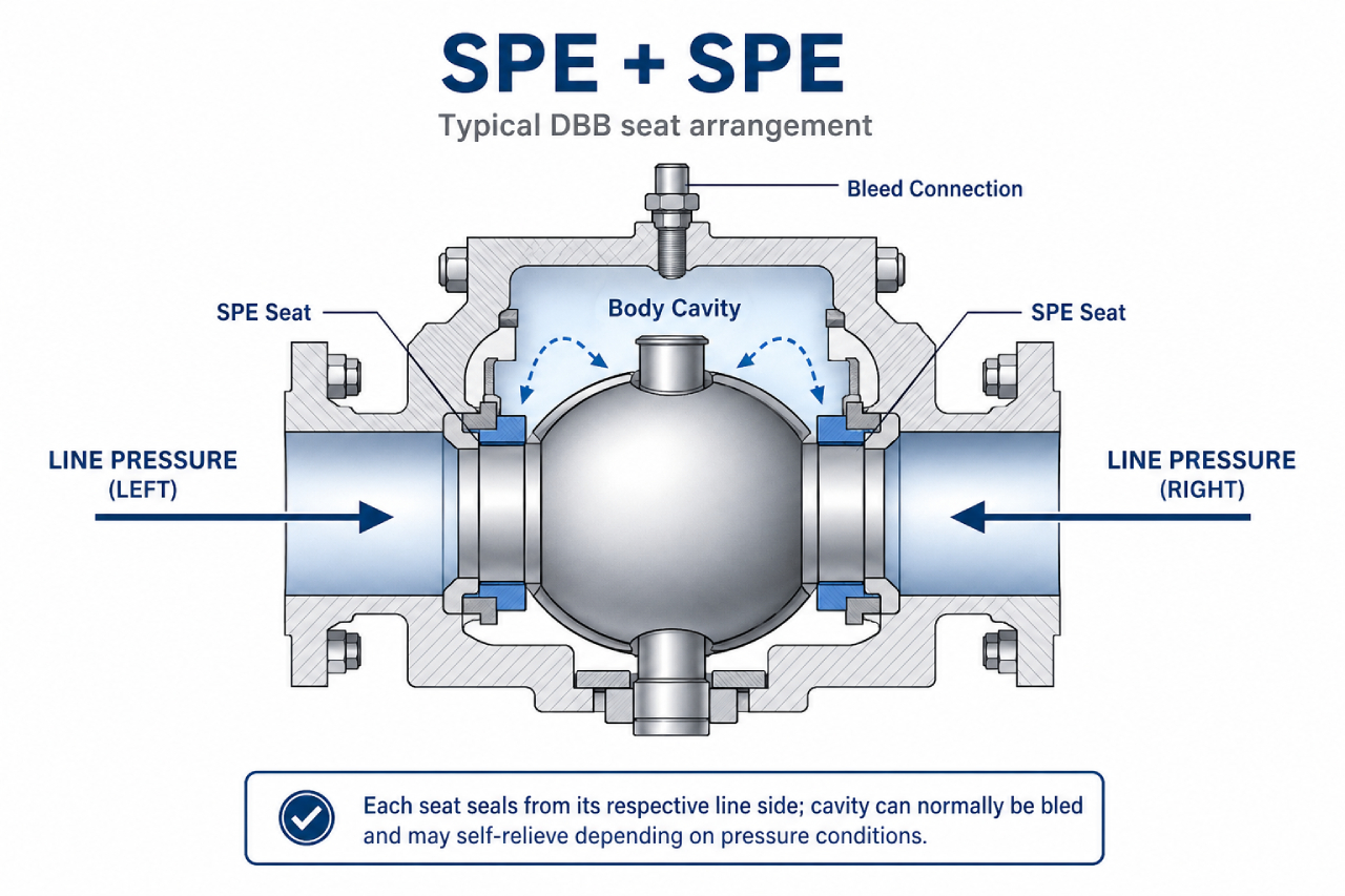
A Single Piston Effect (SPE) seat normally seals when pipeline pressure acts on the line side of the seat.
If body-cavity pressure becomes sufficiently higher than the adjacent pipeline pressure, the seat may move slightly away from the ball and allow excessive cavity pressure to return to the lower-pressure pipeline side.
An SPE + SPE arrangement is therefore commonly used where the valve must isolate pressure from either pipeline end while retaining a bleedable, self-relieving body cavity.
However, if pressure is applied from only one side, this arrangement does not necessarily create two seat sealing barriers against that same pressure source.
DPE + DPE Seat Arrangement
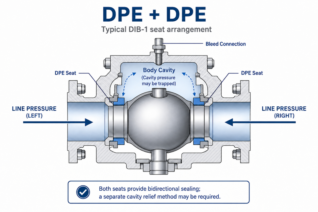
A Double Piston Effect (DPE) seat can seal when pressure acts from either side of the seat.
With DPE seats on both sides, two seat sealing barriers can isolate pressure from either end of the valve. This arrangement is commonly associated with DIB-1.
The same bidirectional sealing behavior can also trap pressure inside the body cavity. If liquid is trapped and subsequently heated, thermal expansion may create excessive cavity pressure.
For this reason, a separate cavity-relief arrangement may be required when a DPE + DPE seat design is used.
SPE + DPE Seat Arrangement
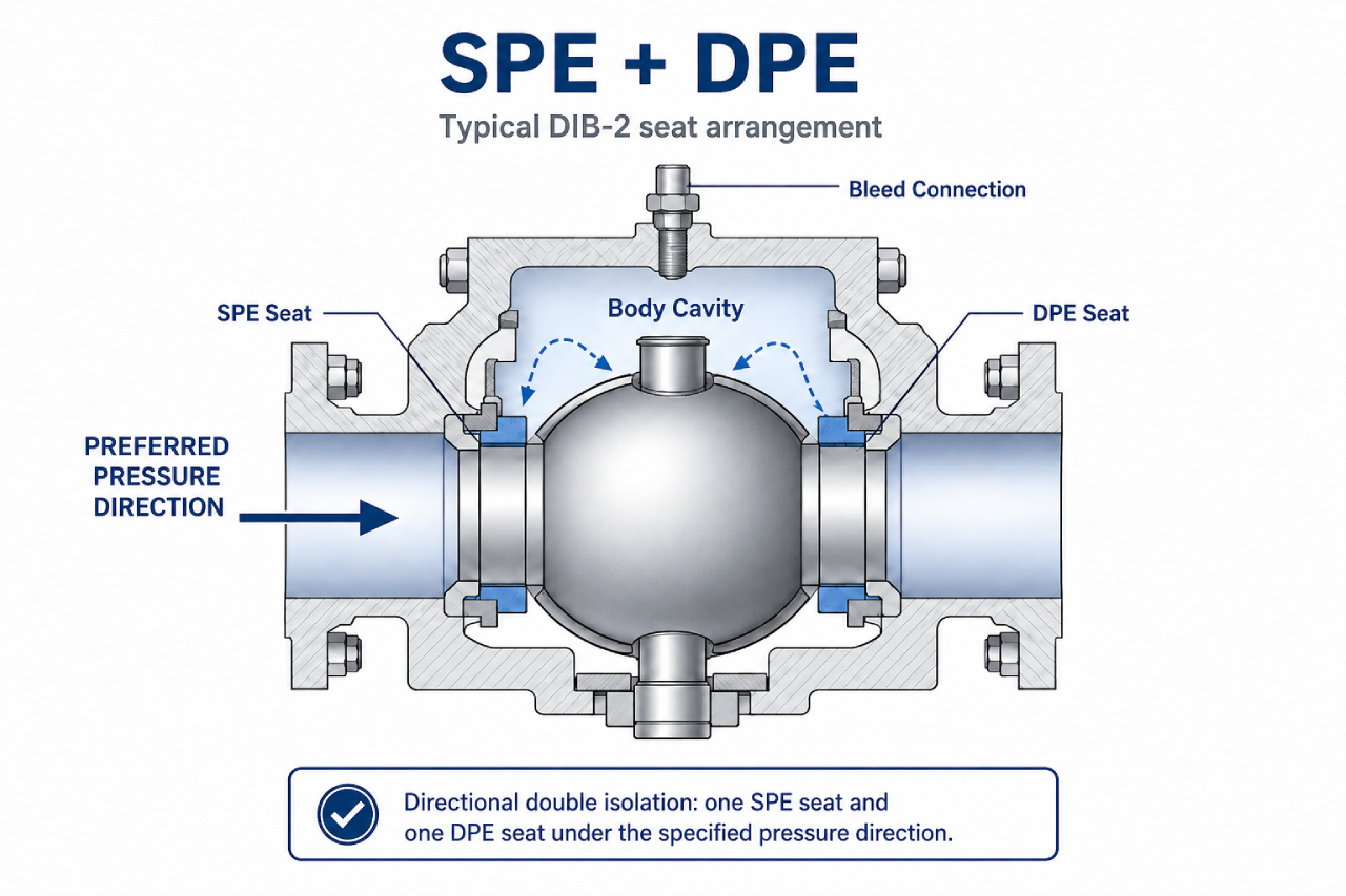
DIB-2 commonly combines one unidirectional SPE seat with one bidirectional DPE seat.
Under the designated pressure direction, the SPE seat forms the first sealing barrier between the pressurized line and the body cavity. If pressure passes into the cavity, the DPE seat can seal against cavity pressure and provide the second barrier toward the downstream side.
Unlike DIB-1, this double-isolation function is normally directional.
The valve orientation, pressure-direction marking and operating instructions should therefore clearly identify the intended installation direction.
Depending on the complete valve design and operating conditions, the SPE seat may also provide a route for excessive cavity pressure to return to the pipeline.
Why Pressure Direction and Cavity Relief Matter
DBB, DIB-1 and DIB-2 cannot be evaluated correctly without understanding how pressure may act on the valve.
The required configuration may change depending on whether pressure can come from either end, whether both sides may remain pressurized, or whether two seat sealing barriers are required from only one designated side.
Body-cavity pressure management is equally important. Some arrangements can relieve excessive pressure through a self-relieving seat, while others require an external relief valve or another project-specific pressure-relief method.
For example, an SPE + DPE arrangement may provide two barriers when pressure comes from the designated side, but the same isolation function may not be available when the pressure direction is reversed.
For this reason, a catalogue statement such as "SPE/DPE available" does not provide enough information for final project selection.
DBB and DIB Describe Functions, Not the Number of Balls
DBB and DIB describe isolation functions. They do not simply indicate how many balls are installed inside the valve.
A single-ball trunnion-mounted valve may provide DBB, DIB-1 or DIB-2 functionality through different seat arrangements.
An integrated twin-ball DBB valve uses two physical ball closure elements with an intermediate bleed chamber. It should be evaluated separately according to the project isolation philosophy, operating procedure and verification requirements.
Why the Sectional Drawing and Test Procedure Matter
The most reliable way to evaluate a DBB or DIB valve is to review its sectional drawing together with the proposed test procedure.
The drawing should clearly identify the seat types, sealing directions, upstream and downstream orientation, body cavity, bleed connection and cavity-pressure-relief path.
Testing should reproduce the actual isolation function required by the project. Depending on the designation and seat arrangement, a seat may need to be tested from the pipeline side, the cavity side or both directions. Leakage is normally monitored through the body cavity or bleed connection.
The agreed test procedure should define the test medium, test pressure, pressure direction, holding time, leakage acceptance criteria and the method used to monitor the cavity.
Where an external cavity-relief device is included, the procedure should also specify whether it remains installed or is isolated during testing.
A valve should not be accepted as DBB, DIB-1 or DIB-2 solely because those terms appear in a product title. Its seat behavior and isolation performance should be demonstrated by the drawing and the agreed verification procedure.
DBB / DIB Selection Checklist
Before selecting a DBB or DIB ball valve, the following information should be reviewed:
- Required isolation function
- Pressure direction
- Seat arrangement: SPE / DPE
- Body cavity relief method
- Medium and operating temperature
- Valve size and pressure class
- End connection and pipeline standard
- Test medium and test pressure
- Leakage acceptance criteria
- Approved sectional drawing
- Project specification and datasheet
This checklist helps ensure that the selected valve matches the actual operating and maintenance requirements rather than only the product name.
Which Configuration Should Be Reviewed?
| Project Requirement | Configuration Normally Reviewed |
|---|---|
| Isolation from both pipeline ends with a bleedable and normally self-relieving body cavity | DBB / SPE + SPE |
| Two seat sealing barriers required against pressure from either direction | DIB-1 / DPE + DPE |
| Two seat sealing barriers required from one designated direction, with a self-relieving path | DIB-2 / SPE + DPE |
This table provides general selection guidance rather than a final specification.
The final configuration remains subject to the valve design, pressure direction, operating conditions, applicable standard, approved sectional drawing and agreed test procedure.
FAQ: DBB and DIB Ball Valves
Is a DBB valve the same as a DIB valve?
No. DBB and DIB describe different isolation functions. A DBB valve may isolate pressure from both pipeline ends and allow the body cavity to be bled, while a DIB valve is selected when two seat sealing barriers are required against the same pressure source.
Does a DBB valve always have two balls?
No. DBB describes an isolation function, not the number of balls. A single-ball trunnion mounted ball valve may provide DBB functionality depending on its seat arrangement, pressure direction and test procedure.
What information is needed to select a DBB or DIB ball valve?
The valve datasheet, medium, pressure direction, seat arrangement, cavity relief requirement, pressure class, test procedure and leakage acceptance criteria should be reviewed before selection.
Reviewing DBB and DIB Valve Requirements with SLVCN
SLVCN can review DBB and DIB valve requirements according to the project specification, expected pressure direction, seat arrangement, body-cavity pressure management method and testing requirements.
The technical proposal should clearly identify the proposed seat design, sealing directions, valve orientation, cavity-relief method and applicable verification procedure before the configuration is finalized.
SLVCN provides API 6D trunnion mounted ball valves, DBB ball valves, forged steel ball valves, fully welded ball valves, top entry ball valves, cryogenic ball valves, metal seated ball valves and customized valve solutions for oil and gas, refining, petrochemical, LNG, power generation and severe service pipeline applications.
Share your valve datasheet, piping specification or operating conditions with our team. Based on the available technical information, an appropriate valve structure and seat arrangement can be evaluated before the technical and commercial proposal is prepared.
Correct DBB or DIB selection begins with understanding the required isolation function, not simply choosing a product label.